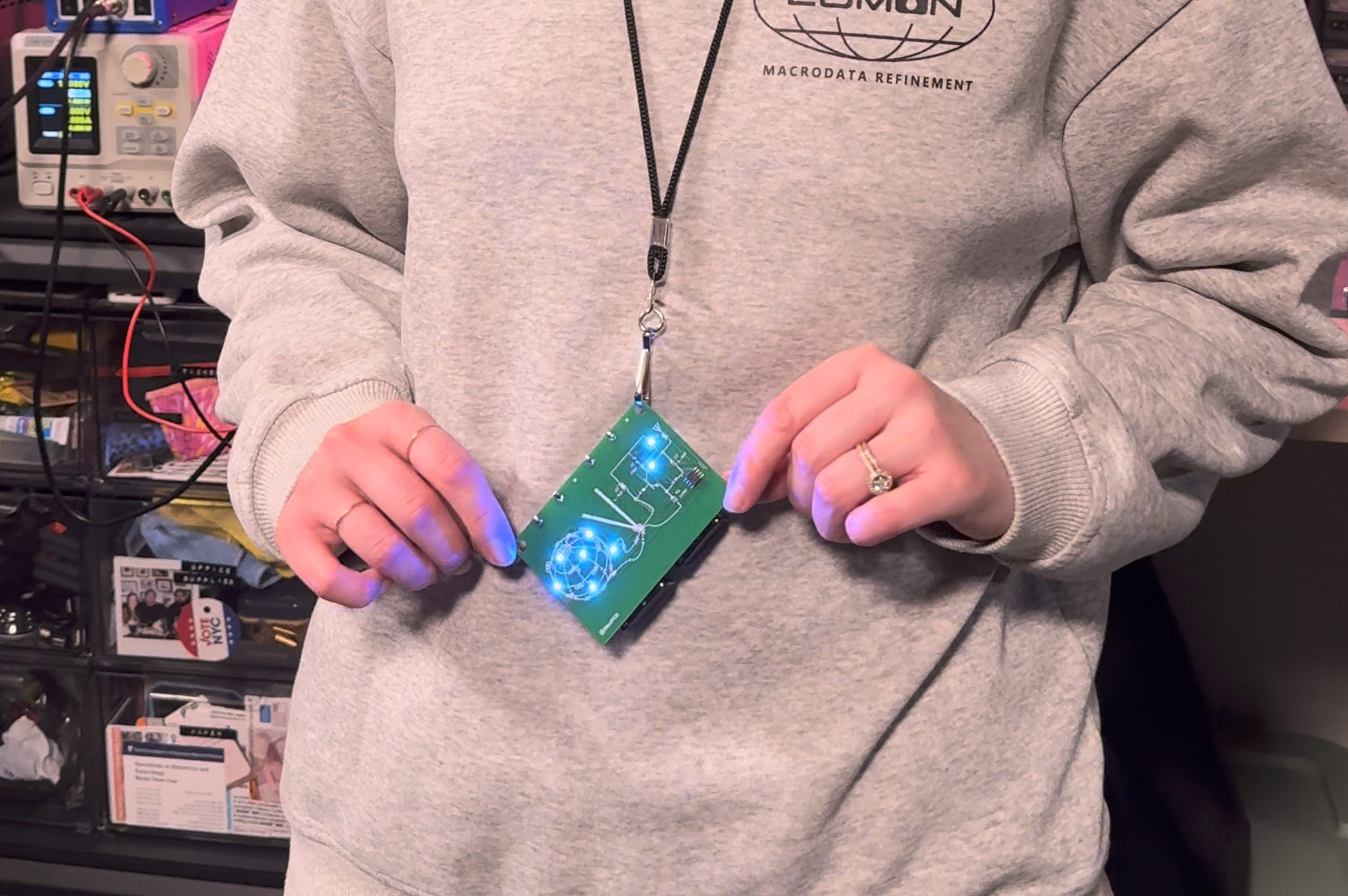
I've been attending Open Sauce for the past few years and have always enjoyed the self-assembled PCB badge. It's such a fun little side quest to find who is handing out the components and which booth has the soldering stations. And since I've had so much fun and gotten so much out of Open Sauce these past few years, I really wanted to contribute something back this year. An add-on badge was this first thing came to mind because of the main Open Sauce badge and how add-on badges are a thing at other events. So for the past few weeks I had been kicking around ideas in my head for what a good add-on badge might look like.
Then next thing I know, it's July 1st and Open Sauce is a mere 2.5 weeks away. At this point, I didn't have enough time to lay out something with an MPU or FPGA, so I reached into the deep recesses of my brain to dust off my circuits 101 knowledge for a circuit that I could layout fast and that could be fabricated fast.
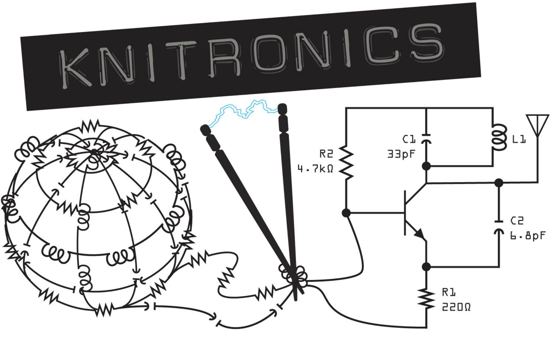
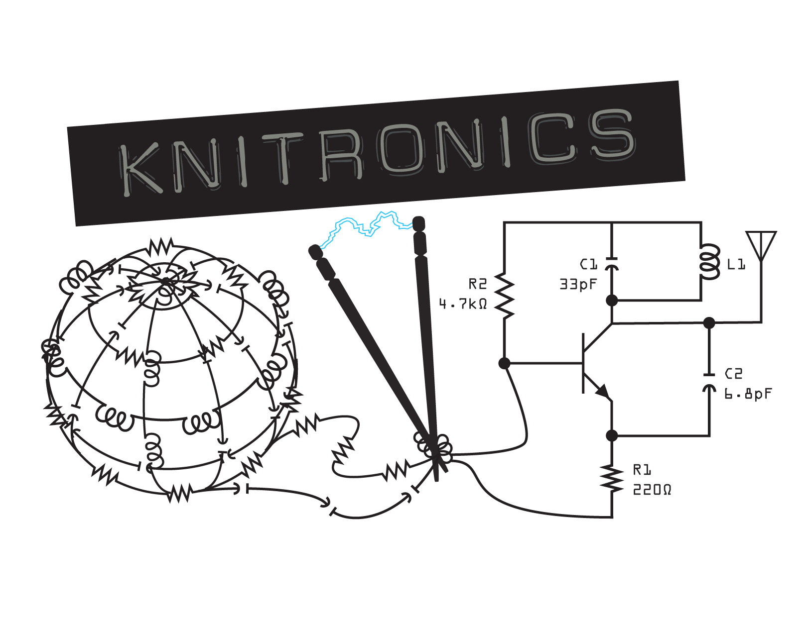
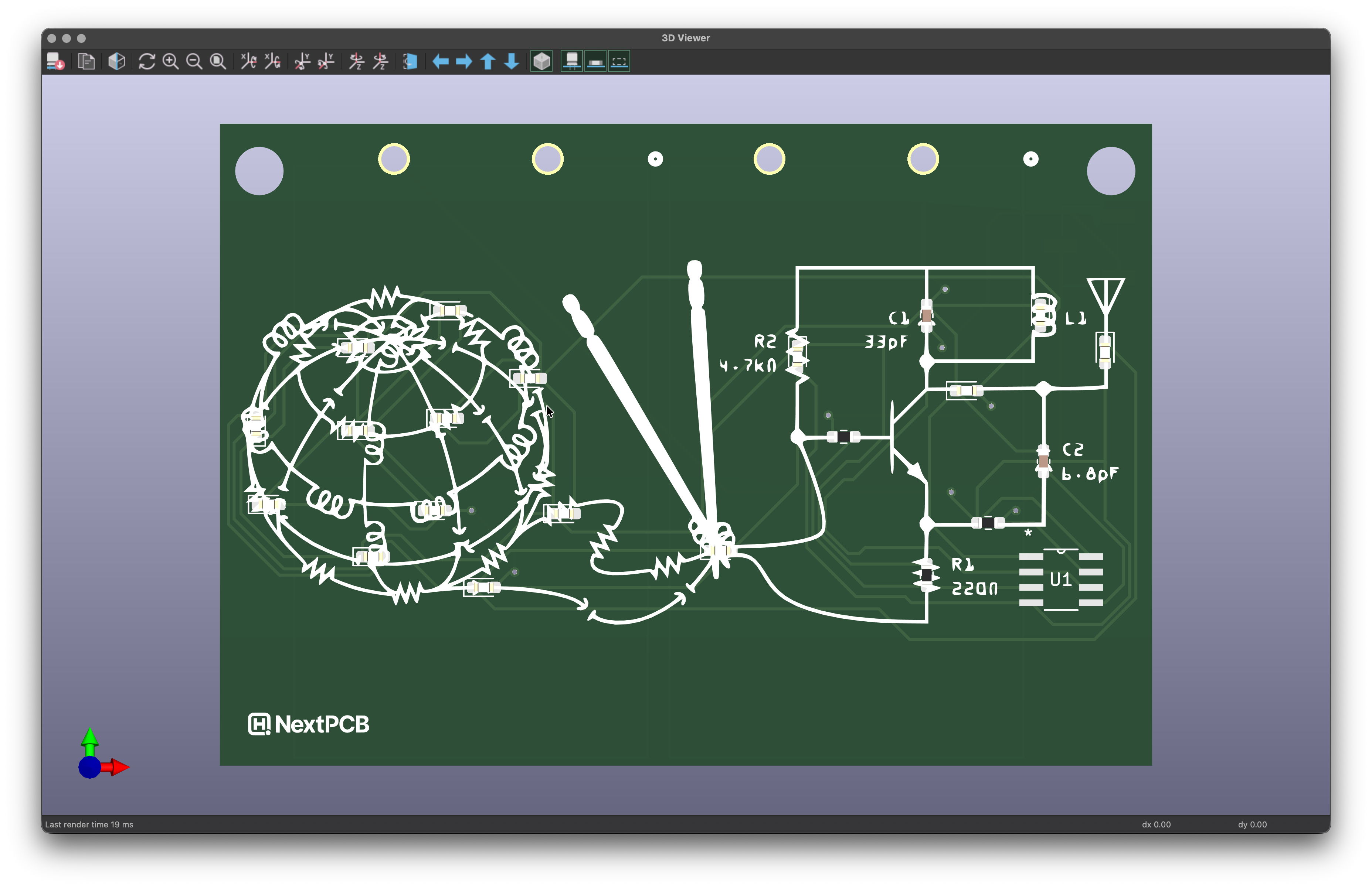
Since I'm a big fan of my logo (I know, I'm a bit biased), I thought it'd be fun to add it to the silkscreen of the board then place actual components over the ones in logo of the circuit that's being knitted. And since it made sense for it to be flashy, an LED flasher circuit was the logical choice.
An LED flasher circuit was also the perfect candidate because it's also simple enough that the layout can be done quickly and fits nicely into a 2-layer board that's fast to fabricate.
2
Build
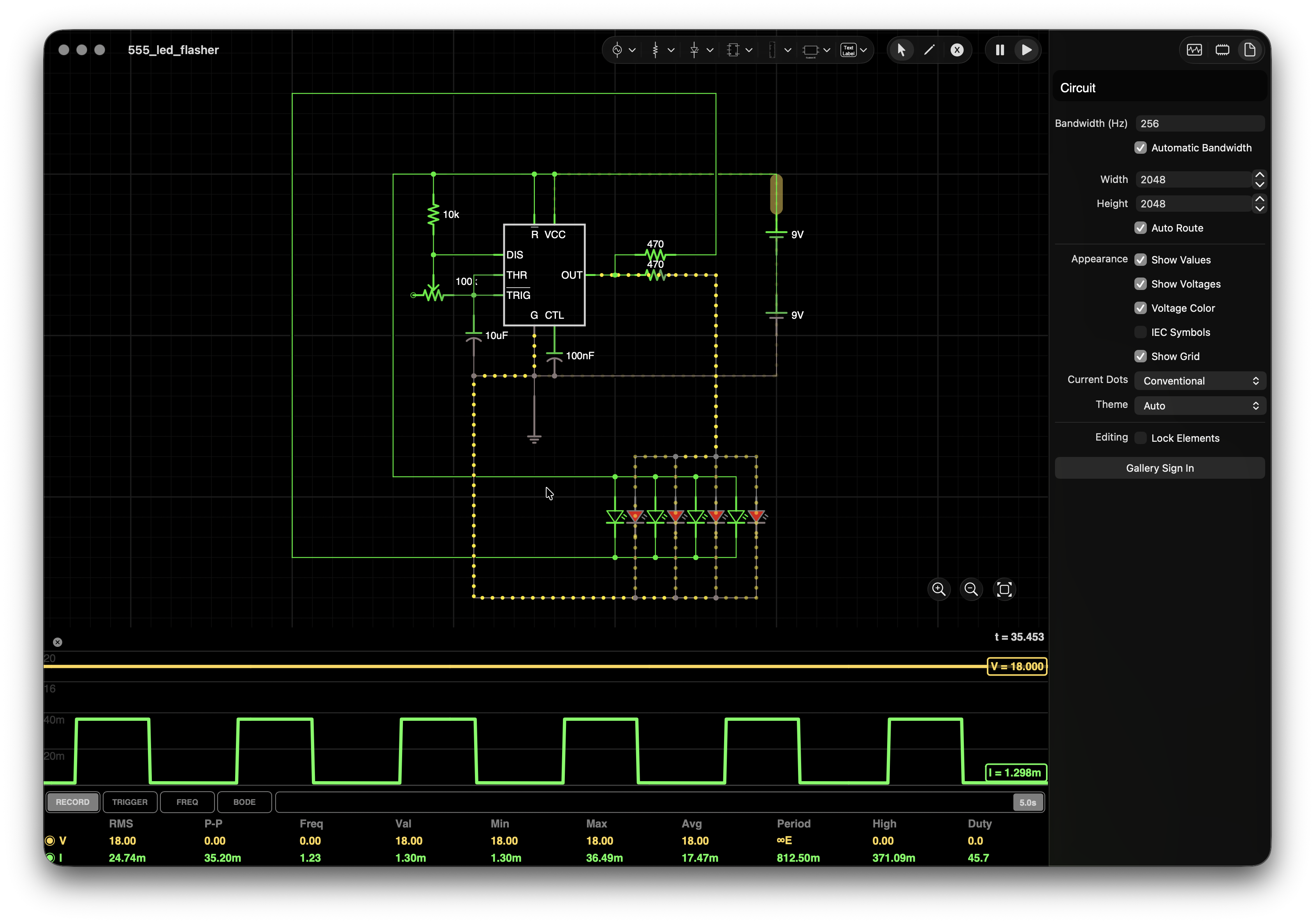
So first things first is simulation, especially since my timeline was so tight here which meant there was no time for a repin of the PCBs if I messed up the circuit. While there are many ways to implement a simple LED flasher, I settled on a 555 timer circuit to output a continuous pulse.
I chose this circuit since I had multiple LEDs to drive on a bus versus just a couple. One 555 timer IC only needs the one RC circuit to generate this pulse so it was the least amount of components needed to drive the most LEDs.
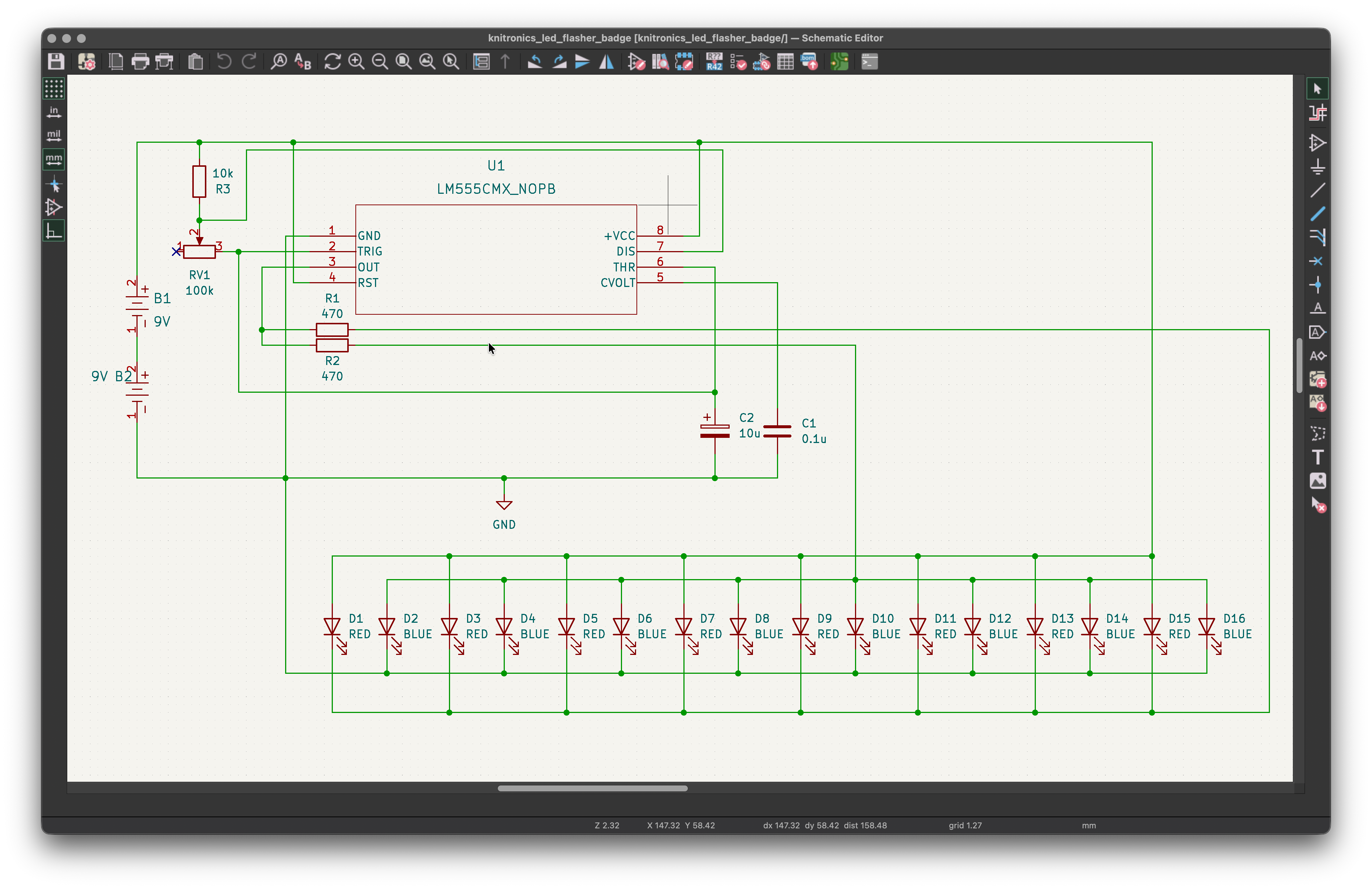
Overall I chose 16 LEDs, 8 red and 8 blue, and put them on two different buses by using two resistors on the output of the 555 timer. R1 connects the negative side of the red LEDs to GND on the high side (Vcc) of the pulse to turn them on, then R2 connect the positive side of the blue LEDs to Vcc on the low side (0V) of the pulse to turn them on.
I found that while the forward voltage of the red LEDs was only 2V and 2.68V for the blue LEDs, since I had them all in parallel I had to increase Vcc of the circuit to 18V in order to get a forward current across each of the LEDS that made them sufficiently bright (8mA - 10mA).
As one final touch in terms of features, I chose to swap the resistor in the RC time constant part of the circuit that controls the width of the pulse on the output of the 555 timer with a potentiometer. This way the user could control how fast/slow the LEDs were flashing.
With the details of the circuit figured out from my simulation, I moved on to building it in KiCad. It only took about 5 minutes to hook everything up in the schematic editor.
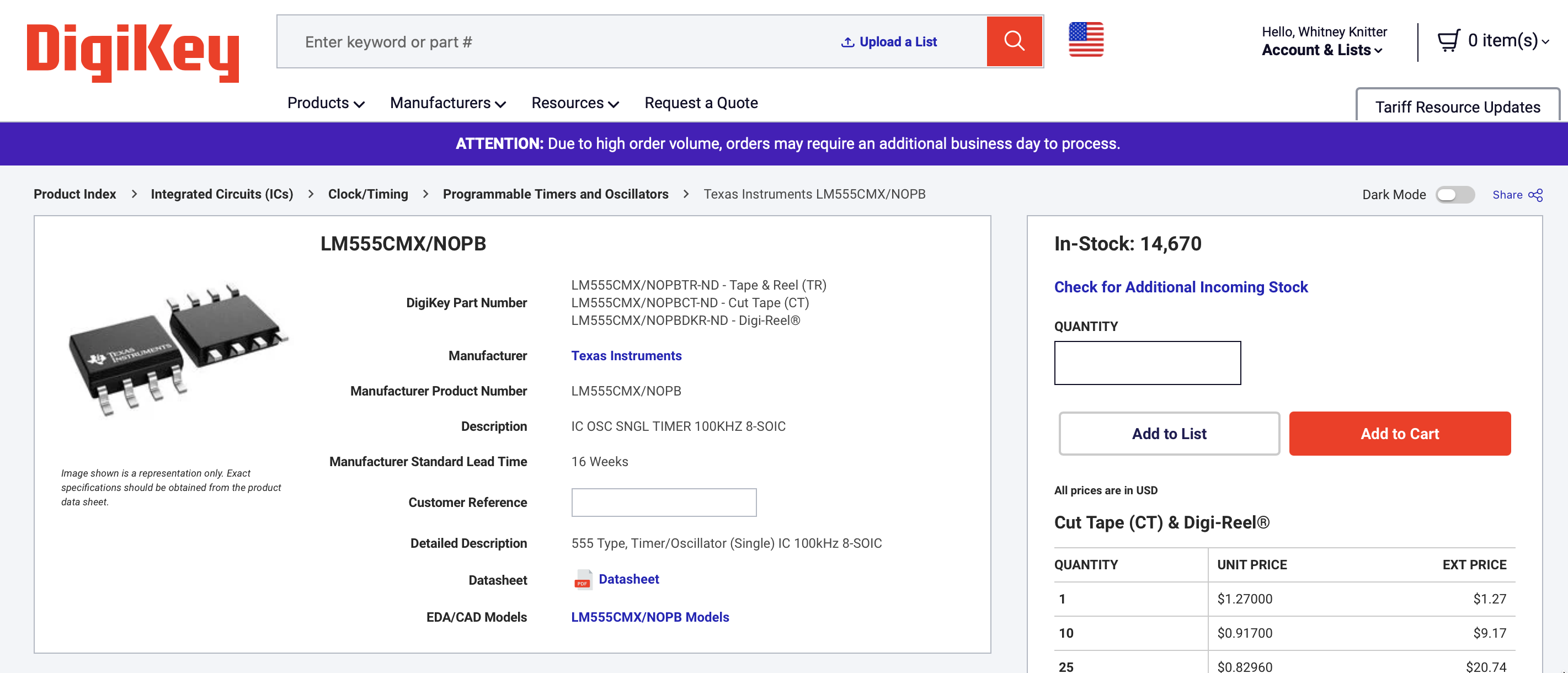
But the real time sink was the selection of the actual components being used. This was in part because I needed to make sure everything I chose was in stock with no lead time so I could get them in time to assemble the boards.
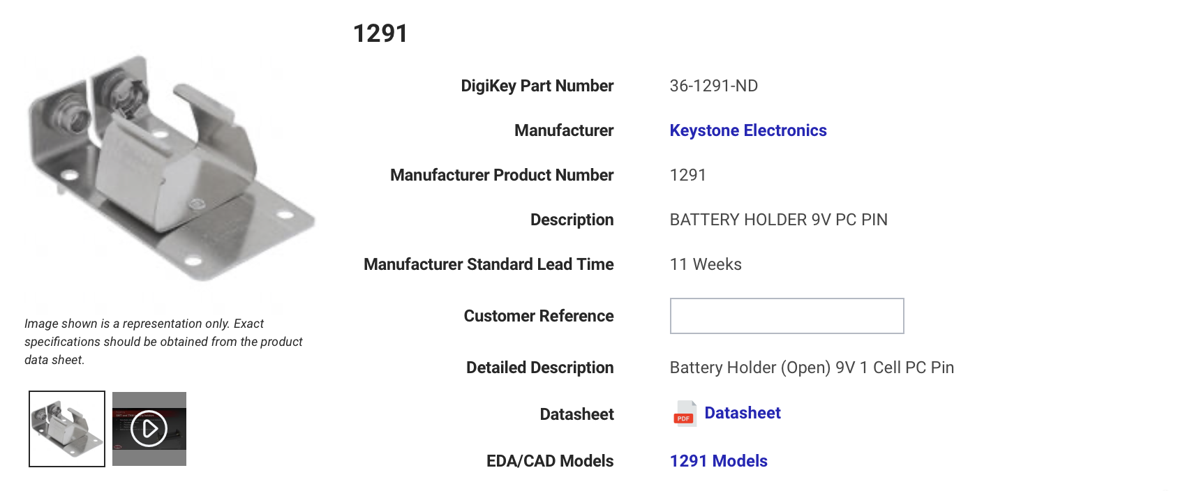
While Ultra Librarian is a great source for finding the footprint/3D models files for layout editors, I like to check if the vendor links the files directly since it saves me a few clicks and guarantees I got the right files for the part I'm using.
In order to supply the 18V the circuit needs, but make it something easy for people to source I chose to add two 9V battery holders that connect the two batteries in series to the input of the circuit.
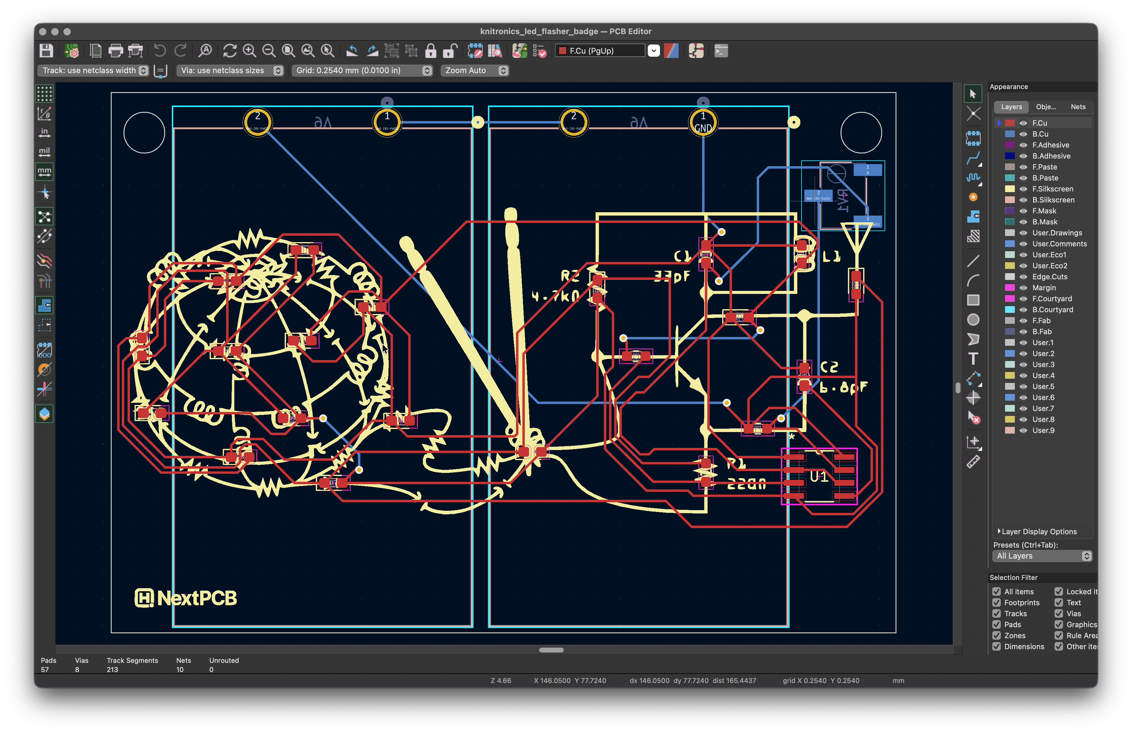
The battery holders are actually what dictated the size of the board itself, I basically made the board just big enough to house the two battery holders and the potentiometer on the back of the board.
The rest of the layout in KiCad was pretty straightforward, although I didn't get away without using a few vias to get all of the LEDs connected to their respective buses.
I used the Image Converter tool in KiCad to import my logo on the the front silkscreen. The only thing to note is that since I placed the LEDs and passive components over the ones on my logo, I did end up with a bunch of warnings in the design rule checker that the solder mask of the components clipped with the silkscreen.
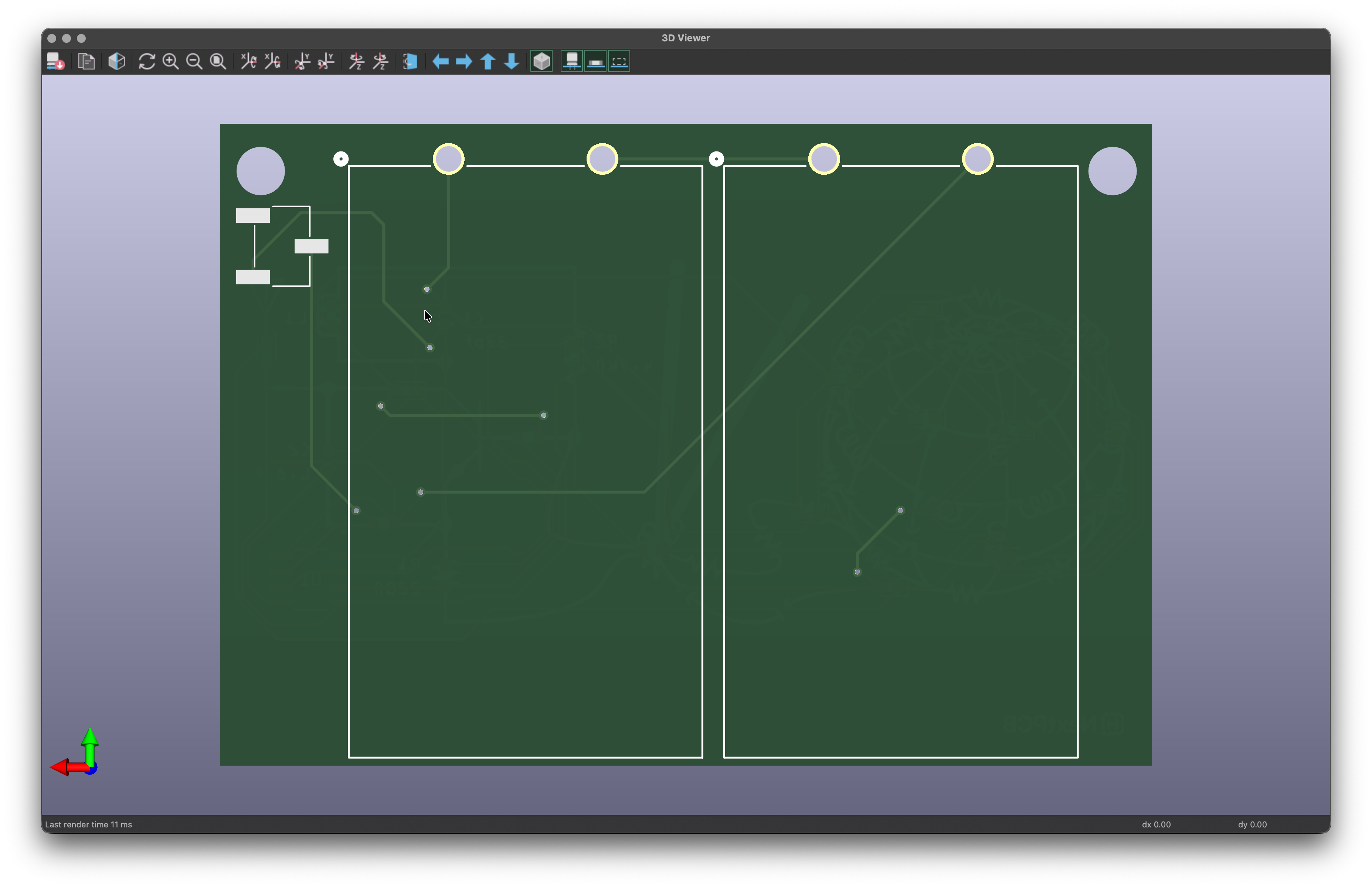
Once I completed the layout, I was able to enjoy my favorite part of KiCad: the 3D viewer of my completed board:
I found the 3D viewer the most helpful to fine tuning the position of the holes in the upper corners of the board for users to clip onto their Open Sauce badges:
At this point, I was ready to send them off to a fab house to be made. This is where NextPCB graciously stepped in and offered to sponsor my boards by both fabricating and assembling them. Then on top of that, they also expedited them to make sure I got them back on time for Open Sauce. So after submitting my gerbers to them on July 1, I received them on my doorstep on July 9.
NextPCB did an amazing job of figuring out how to make these badges happen this year. They reached out when there were a few components they weren't able to source on time and suggested that they leave them unpopulated if I was able to source them myself on time. Which thanks to my careful component selection in the design process, I was able to.
This all turned out so perfectly because the most tedious part of the assembly (all of the LEDs and SMT resistors) was done by them, but the last few components that were the easiest to hand solder (the TH battery holders and the potentiometer) would be left unpopulated for users to solder themselves just like the main Open Sause badge!
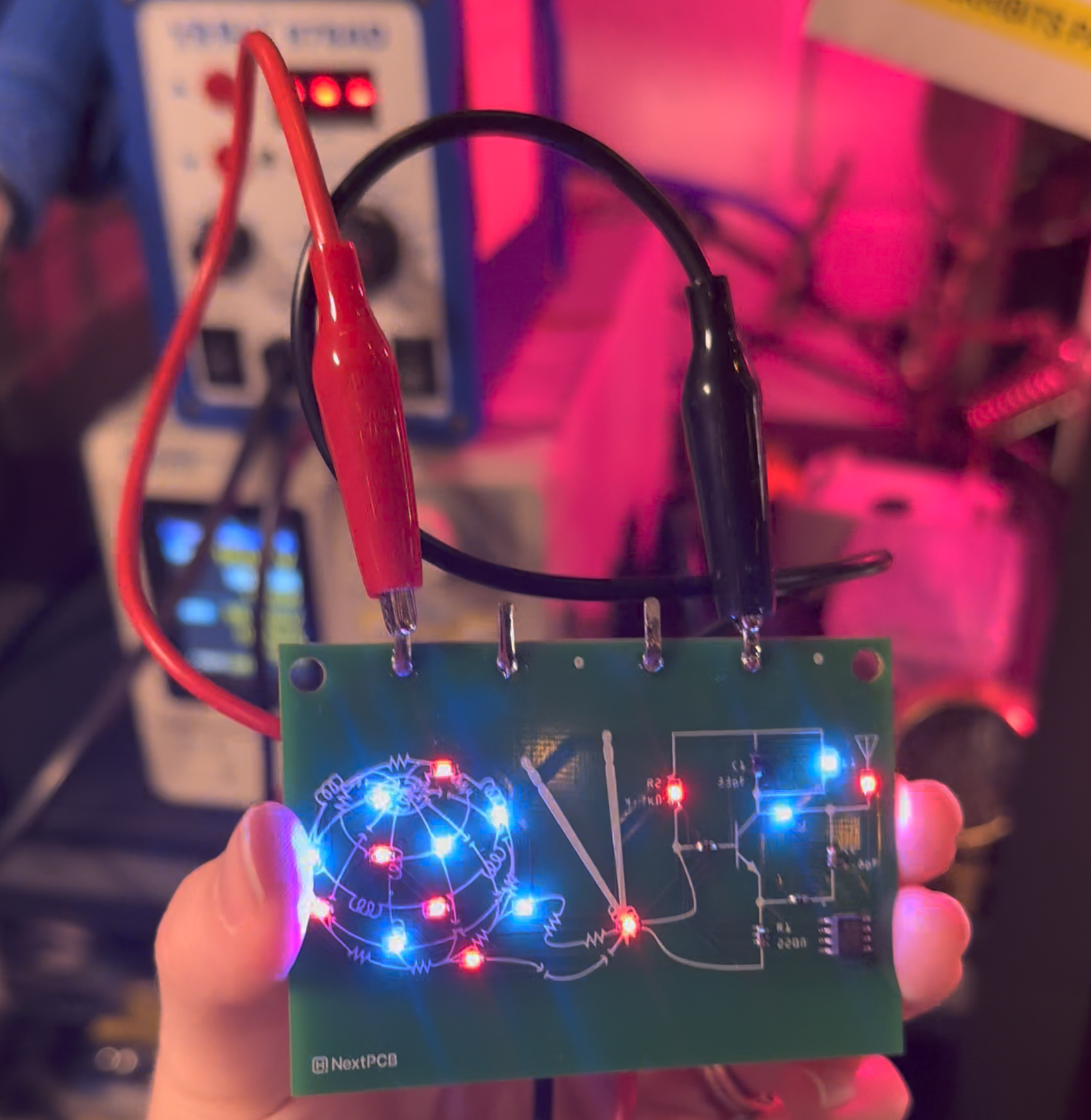
Because I couldn't wait, I soldered up one of the boards and used my power supply to validate it pulled the same amount of current my simulation said it would.
And sure enough, it worked perfectly! If you want to see the details of my soldering it up and testing it, I posted a video about it on YouTube. But if you want one of these badges, be sure to come find me at Open Sauce this year!